Early life defect sites
Scheme information
Transport Scotland provided access to information on each of the identified sites listed in Table 2-1, which included:
- general scheme data, e.g. location, length and completion date;
- construction details, including drawings, schematics, treatment type, and maintenance scheme data (MSD) forms;
- defect data, e.g. date identified, location on carriageway and description or type;
- visual condition data on scheme prior to treatment, including core data, visual condition schematics and images;
- visual condition data post treatment; and
- history of any changes to the original design or treatment proposals that were highlighted as part of Transport Scotland’s internal review process.
Site visits
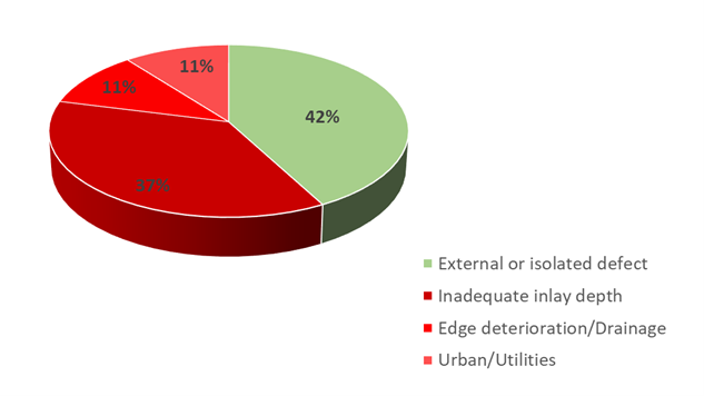
All the sites listed in Table 2-1 were visited and inspected, and brief summaries of the site details are provided in Appendix B. The findings of the surveys were analysed along with the scheme data described above. Based on this analysis, the defects within these sites were split into four broad groups:
- External or isolated defect
- Inadequate inlay depth
- Edge deterioration/Drainage
- Urban/Utilities
Figure 3-1 shows the proportion of sites that fell into these four groups and the findings of the site visits under these categories are discussed in more detail below.
External or isolated defect
In general, the site visits confirmed that most of the defects recorded on IRIS could be located during the survey. However, it became clear that in many instances the defects were not directly associated with the maintenance scheme. In reality, the site visits highlighted that the documented defects were just outside or external to the pavement area treated. It was also observed that on some schemes, a single defect or cluster of defects was limited to a very small area. From the 19 sites visited, 8 sites (42%) were assessed to have external or isolated defects.
External defects
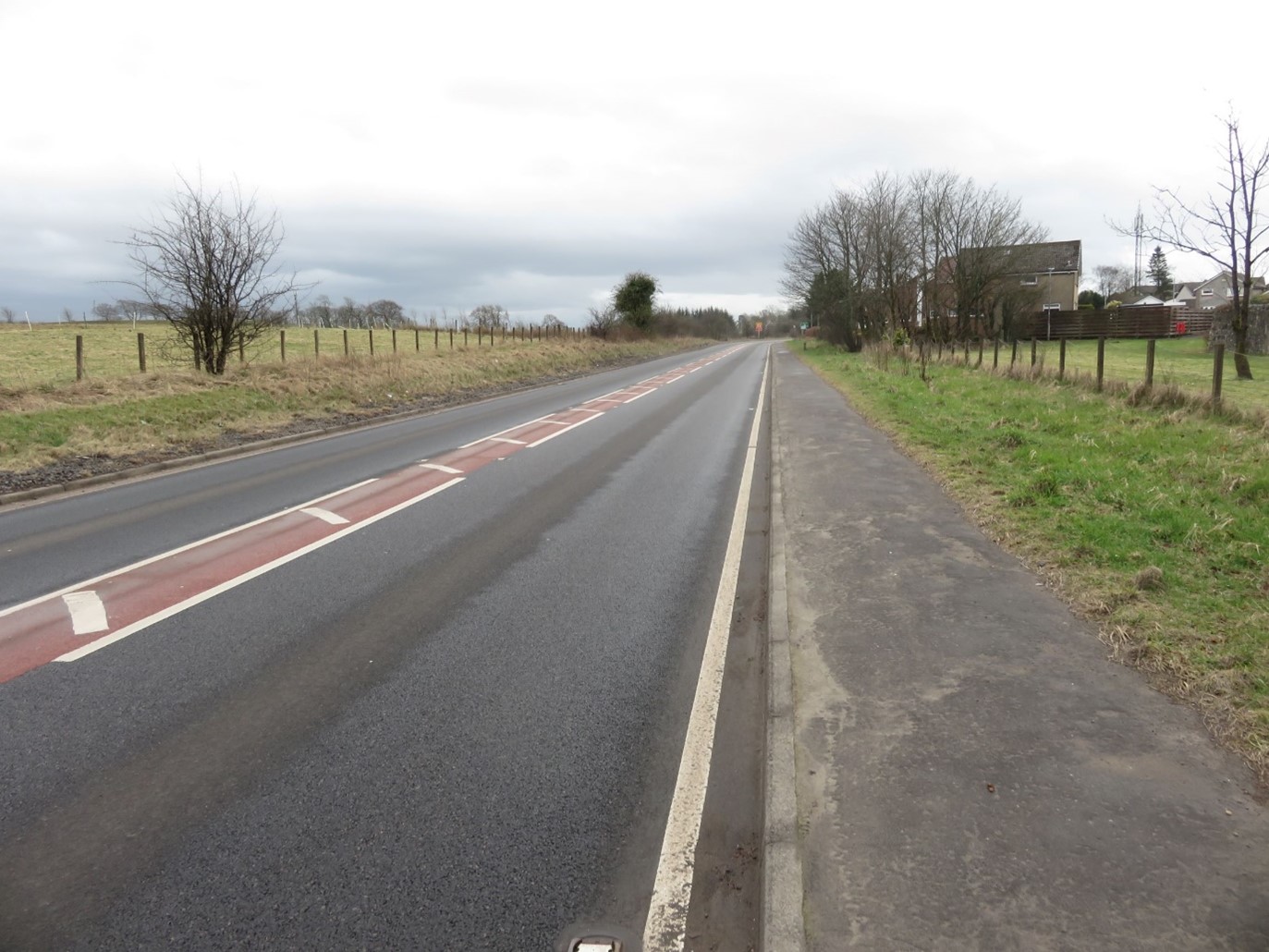
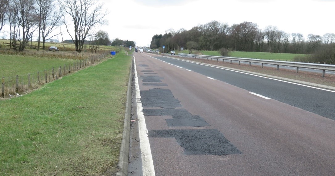
Five of the schemes visited incorporated a targeted design approach that included treating the pavement to different depths, or no treatment. In the latter case, sections of the pavement within the scheme were not treated and presumably deemed to be defect free at the time of the design. The schemes included both single and dual carriageways. Figure 3-2 shows an example of a section omitted for treatment on a single carriageway scheme. Recorded defects were typically found close to the boundary of these sections, i.e. start, end, or adjacent to longitudinal joints, but external to the treated area. The site visits also confirmed that defects recorded on three schemes were confined to bridge deck areas that had not been treated as part of the maintenance works.

Isolated defects
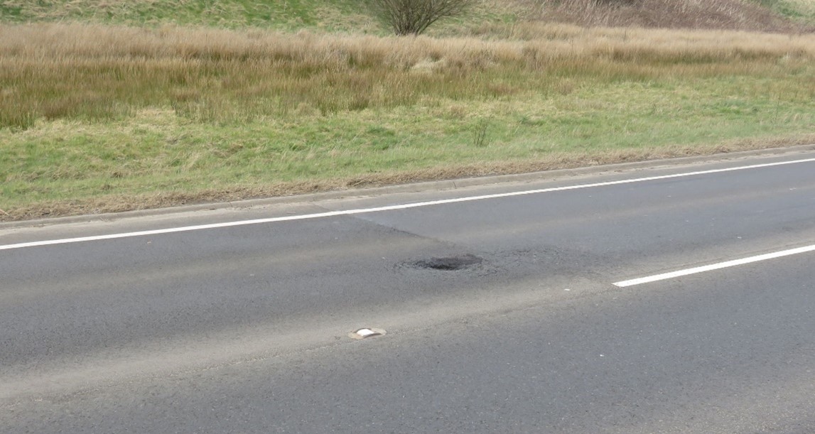
Three of the maintenance schemes exhibited defects that were confined to a very small area. These sites were assessed to be in excellent or good condition with the exception of an odd defect or fault. An example of this type of site is shown in Figure 3-3. The scheme on the A95 near Beith was 868 m long and only one pothole (see insert) was found within the boundary of the treated area.
The cause of these isolated defects is often associated with workmanship and quality control during laying operations. For example, it is known that if spills or cold material clumps from asphalt trucks are not removed immediately then these can cause potholes.
Inadequate inlay depth
One noticeable trend from the sites visited was the occurrence of defects in areas where a shallow inlay had been selected. This was evidenced by the fact that deeper inlays used on the same scheme showed no defects. This observation was also verified where deeper inlays had been successfully used to repair failed areas that contained a thin or shallow inlay. Possible failure mechanisms associated with schemes treated with a shallow inlay are discussed below.
Weak or damaged substrate
Seven of the schemes visited (37%) exhibited defects in areas where a shallow inlay had been selected in preference to a deeper inlay. The schemes that fell into this category covered the four operating areas. A review of the scheme designs, in combination with observations made from the site visits, suggested that the possible reasons for the early life defects could be due to one or a combination of the following factors:
- Selected treatment depth did not fully remove all of the defective or deteriorated material.
- Planing operations may have left behind a weakened material substrate, i.e. the substrate comprised aged (oxidised) material, possibly containing micro-cracks.
- Insufficient bond existed between the new material and substrate, or substrate and lower pavement layer.
The chosen depth of an inlay is likely to be driven by visual condition surveys (VCS), extracted cores and deflection data, where available. VCS data for one of the schemes visited shows that the main driver for maintenance was surface fretting. Figure 3-4 shows the condition of the surfacing in 2016, prior to treatment in 2017, and Figure 3-5 shows an image taken in 2021, post treatment, at approximately the same location.
The appearance of the pavement in 2016 shows a fretted surfacing with extensive aggregate loss. It is possible that owing to the porous nature of this surfacing that the underlying layer was exposed to water and weathering effects. It is possible that the removal of this surfacing, by planing to a depth of 40 mm, left behind a weak or weakened substrate. A similar scheme on the A9 near Blackford exhibited similar defects which were replaced with a deeper inlay with no further deterioration occurring.
A scheme visited on the A77 near Maybole had been reported to experience widespread early life defects a few months after completion in 2017. The defects were only found where a 40mm treatment had been carried out, i.e. none of the deeper treated sections of pavement exhibited any defects. An extensive pavement investigation was carried out in 2019 that concluded that the process of milling operations and exposure to light precipitation had activated a clay mineral within the exposed layer or substrate and subsequently affected the bond to the new asphalt layer. The site visit showed that where these areas had been replaced with a deeper inlay the surfacing showed no defects. However, some small areas suspected to still contain a shallow inlay are continuing to deteriorate (Figure 3-6). Three other sites on the A77, A1 and A82 highlighted that the majority of defects were confined to areas where a shallow (40 mm) inlay had been selected.
Use of thin inlays
A scheme on the A1 involved replacing the failure of a 1 km section of microsurfacing that had begun to delaminate from the surface. The treatment included a 25mm inlay across most of the scheme with a deeper 100 mm treatment over one 150 m section. Shortly after completion in April 2018, defects began to appear in areas that had received the shallower treatment. The site visit in 2021 confirmed that the deeper treatment showed no defects. It was also clear that extensive remedial work (deeper treatment) had been carried out on the site, but the surfacing still appeared to be failing in areas that contained the thin inlay.
Coring data for this site shows that the layer directly below the microsurfacing is a hot rolled asphalt (HRA). The cores show that material layer thicknesses vary, but on average the microsurfacing appears to be around 10 mm thick and the underlying HRA 40 mm thick. Assuming the planing operation was set to mill the material to a depth of 25 mm, it would have left behind a nominal thickness of 25 mm of existing age-old HRA. This is likely to have provided a weakened substrate or support for the newly installed inlay. It is likely that this aged and weakened layer would contain microcracks following milling and constitute a plane of weakness.
It is possible that the new 25mm thick surface course may have slid upon the weak layer below. As a result, excessive flexure in this 25 mm layer would cause the material to crack and break up. An image of the ongoing surfacing deterioration at the A1 is shown in Figure 3-7. Once deterioration commences it is difficult to ascertain the exact failure mechanism, but there are some signs of slippage cracks, represented by crescent-shaped tears, and these are highlighted in Figure 3-7 with dashed red lines. It is likely that the new surfacing material is continuing to move or slide under wheel loads owing to a lack of bond and support from the underlying HRA.

Edge deterioration and drainage
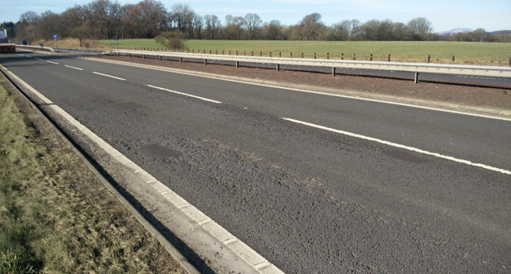
Defects at two of the sites visited were predominantly related to edge deterioration. Figure 3-8 and Figure 3-9 show examples of edge deterioration on the A95 and A82, respectively. Heavy goods vehicle (HGV) tyre marks could be seen clearly at both locations.
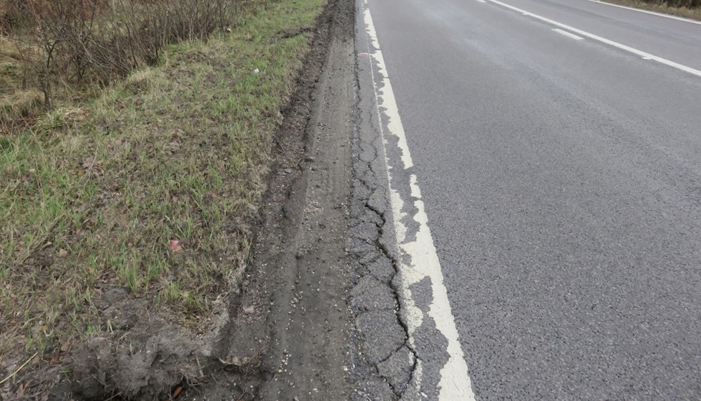
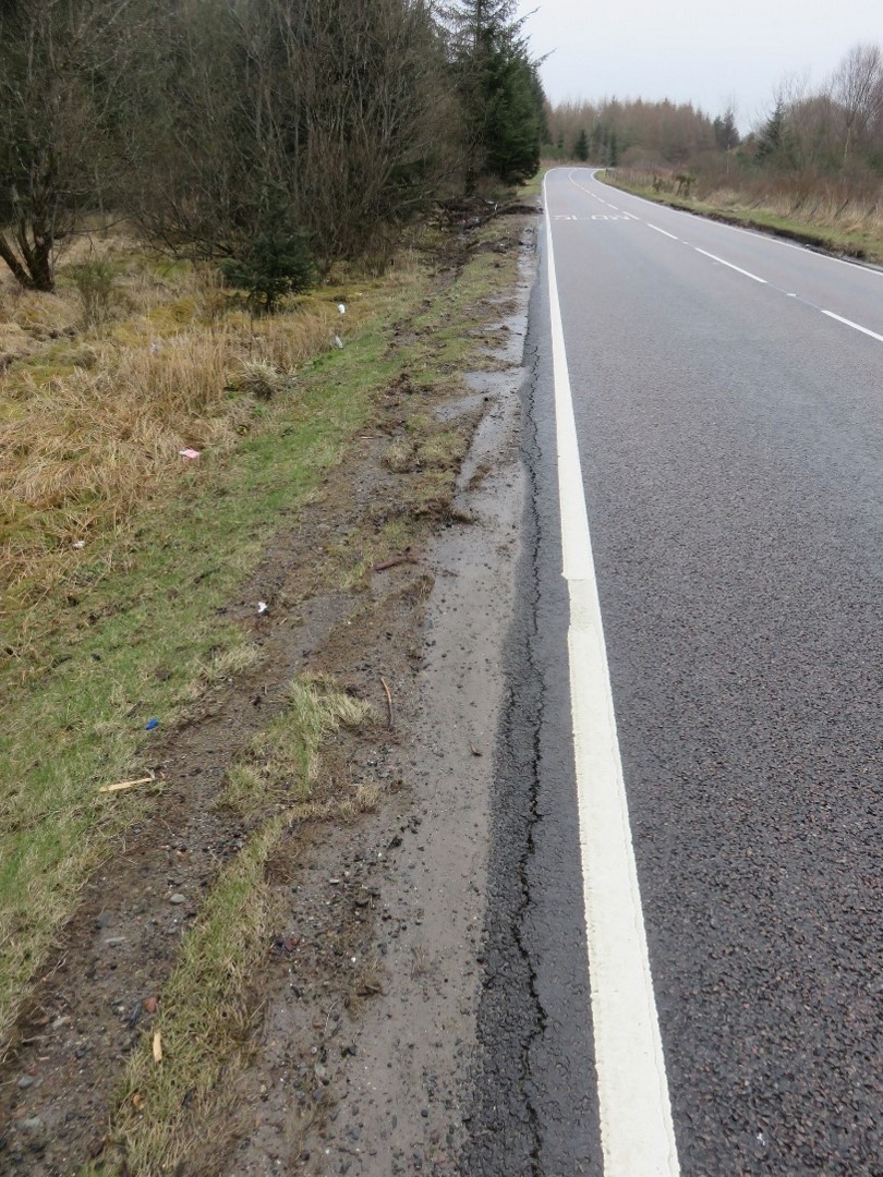
Some of the cracking at the A82 site near Aonach Mòr was more linear in nature and could be due to the presence of a reinforced concrete slab which is located below the upper asphalt layers. However, both these roads comprise long narrow sections (6m width) and will struggle to accommodate two large HGVs passing, particularly if they are carrying a wide load. In addition, both roads provide little lateral restraint in terms of kerbing or drainage. The latter means that they are more vulnerable to edge damage which permits the access of water and further material breakdown.
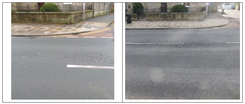
Urban/utilities
Two of the sites visited were located in urban areas. Images taken prior to structural maintenance show a high density of utility reinstatements and street furniture. Defects observed during the site visits were related to damage surrounding street furniture and deeper structural damage. Historical images show that treatments to a depth of 250 mm in some areas has not solved the deeper rooted problems. These sites present challenging conditions and it is likely that expensive reconstruction is required, involving the removal of soft spots below the bound layers and possible repairs to utility apparatus.
Figure 3-10 shows images of a section of road in Biggar (A702) before and after treatment. From the design drawings this section received a 220 mm inlay, but it can be seen that this treatment has not prevented the pavement failing under load. This area along with several others showed severe ‘alligator’ cracking which is related to inadequate structural support. In this instance the reason for failure is most likely due to a loss of subbase or subgrade support, or the presence of water. The presence of water under a pavement will generally cause the underlying materials to become weak.